DEVELOPMENT PROCESS
The image below details the 6 steps that Benchmark incorporates into the software development lifecycle for all projects.
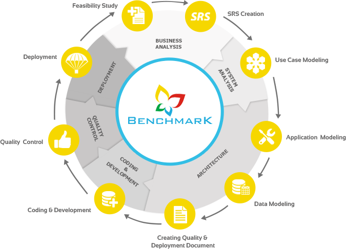
FEASIBILITY STUDY
During this phase, our business analysts defines the scope of the project at hand, who the end users are, any noticeable problems and opportunities, business and technical constraints, apparent project goals, and possible solutions. The end result is a feasibility study that produces a preliminary cost-benefit analysis report. This report will enable us to determine whether significant resources should be dedicated to the other phases of this project.
SOFTWARE REQUIREMENTS SPECIFICATIONS (SRS) CREATION
Gathering the overall total project requirements is one of the most important aspects in any software development process. All of these requirements are gathered and inserted into a document called the Software Requirements Specifications (SRS). This document will contain the functional requirements of the project and how the developers will enhance the project to achieve all the objectives. The Software Requirements Specifications in general serves as a guide for both the client and the developers. It is used for ongoing maintenance on the project as well as the base document for generating the validation and acceptance tests. The Software Requirements Specifications mainly addresses the problem domain in which the product will exist. It is the first step in a project that moves it from the problem domain, to the solution domain. The basic Software Requirements Specifications outline contains the following sections:
WRITING USE CASES
Once the software requirements specifications is approved, the next stage is Use Case modeling. Use Case modeling is a form of requirements engineering. It is a different way of eliciting and documenting software requirements. It partitions the system functionality into transactions meaningful to actors, who are idealized users of the system. Use Case describes an interaction with the actors as a sequence of messages between the system, and one or more actors. The term actor includes humans, time, other computer systems, or processes.
The Use Case model is a prime source for objects and classes. It is the primary input for class modeling. The system architect does the Use Case modeling. Once the Use Case model is completely built, Use Cases are mapped with the actual requirements in the software requirements specifications. A Use Case/Requirement matrix is created. This ensures that a Use Case is modeled for every requirement.
DESIGNING USER INTERFACE COMPLYING WITH USE CASES
Based on the written Use Cases, the systems analyst designs the user interface layout of the software. The User Interface is designed in such a way that all the use cases are satisfied through that user interface. This may be the final deliverable interface (Windows Forms/Web Pages), or the dummy user interface with placeholders. Creation of the user interface at this stage makes the requirements clearer to the client.
APPLICATION MODELING
Once the requirements are frozen, and the user interface is finalized, the next stage is to model the entire application. Unified Modeling Language (UMLA) is extensively used for modeling the application. UML helps you specify, visualize, and document models of software systems, including their structure and design.
Any precise model must first define the key concepts of the application, their internal properties, and their relationship to each other. This set of constructs is the static view. The application concepts are modeled as classes. Each of these classes describes a set of discrete objects that hold information, and communicate to implement behavior. The information they have is modeled as attributes, while the behavior they perform is modeled as methods. Object to object relationships are modeled as associations among the classes. The static view is notated using the class diagram. The static view can be used to generate most data structure declarations in a program. (Source: The Unified Modeling Language Reference Manual)
The view of a system of interacting objects is collaboration. It is a context-dependant view of objects and their links to each other, together with the flow of messages between objects across data links. This viewpoint unifies data structure, control flow, and data flow in a single view. Collaborations and interactions are shown in sequence, and collaboration diagrams.
DATA MODELING
To capture fast paced complex businesses, we must consider methods that go beyond traditional ER diagrams. Maximize Technologies depends on Object Role Modeling (ORM) for its data modeling. ORM is a method for designing and querying database models at the conceptual level. Here the application is described in terms readily understood by users, rather than being recast in terms of implementation data structures.
The architect develops an information model by interacting with others who are familiar with the application. Because these subject matter experts need not have technical modeling skills, reliable communication occurs by discussing the application at a conceptual level, using natural language, analyzing the information in simple units, and working with instances (sample populations). Like any good modeling method, ORM is far more than a mere notation. It includes various design procedures to develop and evolve conceptual models.
Once all the facts are expressed and an ORM model is created, tables can be generated automatically. The design of the database is automatically normalized to the fifth normal form. All relationships, constraints, and default values are maintained when the database is created.
CREATING THE QUALITY AND DEPLOYMENT DOCUMENT
During the course of architecting the software, the architect creates the test plans and quality documents. These documents help the Quality Assurance team to test the product thoroughly, and ensure the quality of the product. The architect also generates a deployment plan for the deployment team. The architect uses the deployment diagrams to explain the deployment of the application.
DEVELOPMENT
The conceptual model is handed over to the software developers for coding and developing the application. The developers use cutting edge development tools to convert the conceptual model into a working real life application. Writing an optimized code is the foremost responsibility of a software developer. Best practices and coding standards are followed while developing the application. Every line of code written is properly documented.
QUALITY
Quality assurance is based on the principle that all deliverables from the application shall be independently reviewed, so that defects are identified and corrected as soon as possible.
A strategy for quality assurance may be viewed in the context of a spiral. Unit testing begins at the vortex of the spiral, and concentrates on each unit/component of the software as implemented in the source code. Using the component level design description as a guide, important control paths are tested to uncover errors within the boundary of the module. Testing progresses outwards along the spiral to integration testing, where the focus is on design and the construction of software architecture. Integration testing is a systematic technique for constructing the program structure, while at the same time conducting tests to uncover errors associated with interfacing.
As we move outwards on the spiral, we encounter validation testing where requirements established as part of requirement analysis are validated against the software that has been constructed. Finally, we arrive at system testing, where the software and other system elements are tested as a whole.
DEPLOYMENT
After the entire product is completely tested and approved, the deployment team deploys the product in the target environment as specified in the deployment document. The deployment diagram given by the systems architect during the architecture phase is used to deploy various components of the product in their target environments.